Part 3: Adding the Register Layer
This tutorial walks through a minimal example showing how to use the UVM register layer in the generated code. It differs from the minimal example used in parts 1 and 2 of the tutorial in that we now have to add command, address, and data variables to the transaction sent to the driver in order to support the register reads and writes required by the register layer. We will end up with a user-defined register sequence executing read and write operations through the register layer, which will itself be instantiated within the UVM environment generated by the code generator.
You can download the files for this example. The files are in the directory named ./minimal_reg.
Acquire a Register Model
The register model itself does not come for free! You either have to write it from scratch or, preferably, generate it using one of the many commercially available register generator tools. The register model may be structured any way you like: the only restriction is that there must exist a root address map for each agent in the top-level register block. You can put settings in the template files to select the address map for each agent and also to choose which register block in the hierarchy the regmodel variables of the agent and its sequences refer to.
This minimal example has a single DUT interface named bus, and the register layer has access to a single DUT register of type dummy_reg. The register model looks like this:
Filename regmodel.sv
class dummy_reg extends uvm_reg;
   `uvm_object_utils(dummy_reg)

   rand uvm_reg_field F;
   ...
   virtual function void build();
      F = uvm_reg_field::type_id::create("F");
      F.configure(this, 8, 0, "RW", 1, 8'h00, 1, 1, 1);
   endfunction
endclass
class bus_reg_block extends uvm_reg_block;
   `uvm_object_utils(bus_reg_block)

   rand dummy_reg reg0;
   uvm_reg_map bus_map;
   ...
   virtual function void build();
      reg0 = dummy_reg::type_id::create("reg0");
      reg0.configure(this);
      reg0.build();

      bus_map = create_map("bus_map", 'h0, 1, UVM_LITTLE_ENDIAN);
      default_map = bus_map;
      bus_map.add_reg(reg0, 'h0, "RW");
      lock_model();
   endfunction
endclass
class top_reg_block extends uvm_reg_block;
   `uvm_object_utils(top_reg_block)

   bus_reg_block bus;
   uvm_reg_map bus_map;
   ...
   virtual function void build();
      bus = bus_reg_block::type_id::create("bus");
      bus.configure(this);
      bus.build();

      bus_map = create_map("bus_map", 'h0, 1, UVM_LITTLE_ENDIAN);
      default_map = bus_map;
      bus_map.add_submap(bus.bus_map, 'h0);
      lock_model();
   endfunction
endclass
Add Register Access to the Interface Template File
We start with the main part of the interface template file where the variables in the transaction and the interface are specified. This is very similar to the interface template file from the previous parts of the tutorial, but has some extra variables to allow a memory-mapped interface. To keep the example minimal we only include the driver code (the monitor and coverage code are omitted):
Filename bus.tpl
agent_name = bus
trans_item = bus_tx
trans_var  = rand bit cmd;
trans_var  = rand byte addr;
trans_var  = rand byte data;

driver_inc = bus_do_drive.sv

if_port  = logic clk;
if_port  = bit  cmd;
if_port  = byte addr;
if_port  = byte data;
if_clock = clk
We now extend this interface template file by specifying the kind of access we want the register layer to have and also the mapping between the register layer and the agent, which is specified by identifying the command, address, and data variables (of the transaction) that we want the register layer to use for its reads and writes to registers in the DUT:
reg_access_mode       = WR
reg_access_block_type = bus_reg_block

uvm_reg_kind    = cmd
uvm_reg_addr    = addr
uvm_reg_data    = data
reg_access_mode must specify whether the register layer is to be allowed write/read (WR), write-only (WO) or read-only (RO) access to the registers. reg_access_block_type must specify the type of a uvm_reg_block class in the register model file that encloses the registers that are to be read or written from the register sequence. By default, this is expected to be a register block that is instantiated within the top-level register block of the register model and with its variable name being the same as the agent name, but it is possible to have the register sequences access the registers using object names relative to any register block in the register model, including the top-level register block. To change the default, you would set reg_access_block_instance. (See the Reference Guide for a fuller description of how to use these settings.)
Add Register Access to the Common Template File
Certain aspects of the top-level register model must be described to the code generator in the common template file:
Filename common.tpl
regmodel_file      = regmodel.sv
top_reg_block_type = top_reg_block
The regmodel_file setting is optional and, if present, names the file containing the register model. If this setting is omitted, the register model must have the default file name of regmodel.sv. The top_reg_block_type parameter must pick out the class name of the top-level register block.
Generate and Run
Now we've got all we need to run first the code generator and then the simulation. Here is a script to run the code generator:
perl ../../easier_uvm_gen.pl bus.tpl
All we have needed to do to include the register layer in the generated code is to provide the file regmodel.sv and add a few lines to the template files.
The code generator will create the following structure:
top_tb (module)
 ↳ top_th (module instance)
   ↳ bus_if (interface instance)
     mydut (module instance)

 ↳ top_test (object, class uvm_test)
    ↳ top_config (created in build_phase, class uvm_object)
      top_env (uvm_env)
       ↳ bus_env_config (uvm_object)
         top_reg_block (uvm_reg_block)
         bus_env (uvm_env)
          ↳ bus_config (uvm_object)
            bus_reg_block (uvm_reg_block)
            reg2bus_adapter
            uvm_reg_predictor
            bus_agent (uvm_agent)
             ↳ bus_sequencer
               bus_driver (uvm_driver)
               bus_monitor (uvm_monitor)
            bus_coverage (uvm_subscriber)
            bus_env_coverage (uvm_subscriber)

       ↳ top_default_seq (created in run_phase, class uvm_sequence)
          ↳ bus_env_default_seq (uvm_sequence)
             ↳ registers.update()
Viewed as a diagram, the generated environment for two agents each using a register model would look like this:
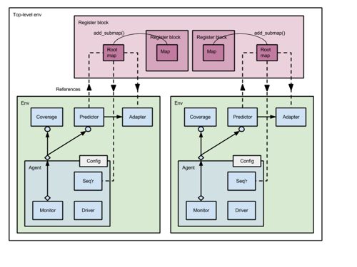
Figure: Connecting the Register Layer
When instantiating a register model, each agent that uses the register model is instantiated within its own env, which means that the generator creates an extra level of component hierarchy (an extra env) around each agent. In the structure above, you can see that:
top_test
  instantiates top_env
    instantiates bus_env
      instantiates bus_agent
top_env has a reference to the top-level register block top_reg_block and is the env in which the entire hierarchical register layer is actually instantiated, including all of its sub-blocks.
bus_env has a reference to the register block bus_reg_block for that specific agent and instantiates the adapter and predictor that will connect that particular register sub-block to that particular agent, as well as instantiating the agent itself, of course. bus_env does not instantiate its own register block, but does connect its register block (one hierarchical part of the overall register layer) to its predictor. The connections are made in the connect_phase method of the bus_env.
The default sequence created by the code generator for any env that uses the register layer will write a random value to every register in the corresponding register block. The body task of that sequence is as follows:
Filename bus_env_seq_lib.sv
task bus_env_default_seq::body();
  super.body();
  `uvm_info(get_type_name(), "default sequence starting", UVM_HIGH)
  regmodel.get_registers(data_regs);
  data_regs.shuffle();
  foreach(data_regs[i])
    begin
      // Randomize register content and then update
      if(!data_regs[i].randomize())
        `uvm_error(get_type_name(), $sformatf("Randomization error for data_regs[%0d]", i))
      data_regs[i].update(status, .path(UVM_FRONTDOOR), .parent(this));
    end
  `uvm_info(get_type_name(), "default sequence completed", UVM_HIGH)
endtask : body
If you run the simulation, you will see a single write to the one-and-only register in the minimal register model.
Add a User-Defined Register Sequence
As with the previous tutorial, you can create your own sequence by extending the default sequence created by the code generator. This time it is specifically a register sequence. Here it is:
Filename bus_env_reg_seq.sv
class bus_env_reg_seq extends bus_env_default_seq;
  `uvm_object_utils(bus_env_reg_seq)
  ...
  task body();
     regmodel.reg0.write(status, .value('hab), .parent(this));
     assert(status == UVM_IS_OK);

     regmodel.reg0.write(status, .value('hcd), .parent(this));
     assert(status == UVM_IS_OK);

     regmodel.reg0.write(status, .value('hef), .parent(this));
     assert(status == UVM_IS_OK);

     regmodel.reg0.read(status, .value(data), .parent(this));
     assert(status == UVM_IS_OK);
  endtask: body
endclass : bus_env_reg_seq
You then include your new sequence and set the factory override by adding lines to the interface template file:
Filename bus.tpl
...
reg_seq_inc       = bus_env_reg_seq.sv
agent_factory_set = bus_env_default_seq  bus_env_reg_seq
You can then run simulation on the generated code out-of-the-box and should see the following lines (from the dummy DUT) included somewhere in the simulation log:
# @10000 mydut bus_cmd = W, bus_addr = 00, bus_data = ab
# @30000 mydut bus_cmd = W, bus_addr = 00, bus_data = cd
# @50000 mydut bus_cmd = W, bus_addr = 00, bus_data = ef
# @70000 mydut bus_cmd = R, bus_addr = 00, bus_data = 00
Prev Next